Working with Components
This page is a general overview of components and assemblies. See Framing System Components for more details on components in systems.
Components are WinBidPro's method of handling part assemblies and condition-specific part counts.
These are instructions that turn individual parts and conditions into counts when applied to your elevations.
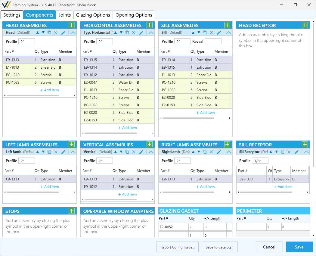
Assembly Components
Assembly components are a group of parts used in a specific assembly, like the head or right jamb of your system. Each assembly component can store multiple assemblies, setting one as the default and using the others as alternates when needed.
Header of these components is used to manage these assemblies, while configuration is handled in a separate window.
-
Component Header
-

Add- Creates a new assembly and opens an assembly configuration window. See Configuring Assemblies below for details. -
Paste- This button appears next to theAddbutton when you copy an assembly from another component. SeeCopybelow.
-
-
Assembly Headers
-
▲Move Up/▼Move Down- Organize your list of assemblies within the component.- The first listed assembly is the default assembly. Any others are available as alternates but are not automatically applied.
-

Copy- Copy the assembly to paste it in another component. SeePasteabove.- Useful for systems with identical left and right jambs, for example.
-
XDelete- Delete this assembly. -

Edit- Open the configuration window for this assembly. -
⋀Collapse/⋁Expand- Show or hide details about this assembly, including a list of parts.- When expanded, you can edit the parts lists using the
Xdelete or+Add itembuttons. You can also change theProfileandRevealwithout having to open the configuration window.
- When expanded, you can edit the parts lists using the
-
Configuring Assemblies
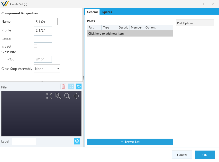
Keep in mind which parts should be added to which component and how it will all come together. Incorrect assemblies can add to or subtract from cuts or glazing areas in your estimates.
For example -- Sill Flashing should be a Sill Receptor component, not a part in the Sill assembly because it interacts with jambs and verticals differently, and it would include that part in the profile height which isn't typical.
Having an elevation open in the CAD viewer can help visualize how everything is coming together. You can even take it a step further with layer settings, and set different colors for different component types.
Component Properties
Assembly components will have the option for a Name and a Profile at a minimum, but assembly components will have different Component Properties based on their type.
For example - framing assemblies (Head, Jamb, Vertical, Etc) will have an option for Glass Bites, but Head and Sill Receptor assemblies won't.
-
Name- A place to name your assembly to help it stand out against alternates in the same list. -
Profile- The height of the visible face of your assembly when looking at it in elevation.
File: - Specify, delete, refresh or upload a CAD detail file. A CAD detail added here will show up in the CAD view just below these options.
Label: - Set a label tag or number.
Part Tabs
Add individual parts of your assembly in the part tabs on the right. These tabs are broken up into general parts and splice parts.
-
General parts are always active.
-
Splice parts only get counted where splices are applied.
Part Options - Select a part to add to set its options like Quantity and Spacing.
Browse List - Browse for parts in your vendor catalog to add to the assembly.
Configure Splice Gap & Offset - Splices Tab only. Opens 3D CAD view of your splice with option to set spacing and offsets for each part. Mainly used in curtain wall and window wall systems to coordinate face covers, pressure plates and back members.
- See Splices for more details.
Keep in mind, these changes effect your estimates so it's important to think through where assemblies meet.
For example -- you'll want to consider when things like fasteners should be included at one assembly or the other, to avoid adding them to both and doubling your counts.
Other Components
Others components are grouped and listed by how they're counted - Per Elevation or Perimeter for example. These are simplified lists of Part Numbers and Quantities that get counted by that condition.
As you type out part numbers here, you'll get a list of partial matches to speed you up.
For length-based conditions, like Perimeter, you'll also get an option to automatically add or subtract inches to each measured length but using the +/- Length box. Use this to help dial in your drops, clean cuts, tolerances, etc.
'Per X' Example
If a Part Number is added with a Quantity of 2 as a Per Elevation component, and you have 10 elevations with that system assigned, your parts list will count 20 of that part.
Length Example
If a Part Number is added with a Quantity of 1 as a Perimeter component, and you have a 10'-0" x 10'-0" elevation, your parts list will count a length of 40'-0" of that part for that elevation.
If you add a +/- Length of -2, it will count 39'-10" instead.