Tips - Cassette Systems
Cassette Systems need some extra set up to account for the separate extrusions at the cassettes, and for the alternate parts at expansion horizontals.
To set this up correctly, we'll make some alt assemblies in Components and build out some options in the Joints and Opening Options.
As you're building out your components, do not include the framing at the cassettes in your framing. We'll be using Opening Options and Stops assemblies for those so we can set them per glass panel.
Additional Configuration Steps
Follow the typical configuration steps for a framing system up to this point, ignoring the glass cassettes when as you do. Then add the following assemblies and options.
-
We'll be using the
Jointstab for these systems, so pay special attention to where you assign hardware in yourComponentstab.- See the Joints Tab page for more details.
Horizontal Assembly
Add an alternate Horizontal Assembly in the Components tab:
Expansion Horizontal - Include parts for the expansion horizontal to be applied at vertical splices.
Stops Assemblies
Create three Stops assemblies in the Components tab or the Opening Options tab:
Standard Frame - These are your default cassette assemblies along one edge of the cassette. We'll be using this for all standard edge conditions.
Expansion Sill - Include the parts needed at the bottom frame of a cassette when an expansion horizontal is below.
Expansion Head - Include the parts needed at the top frame of a cassette when an expansion horizontal is above.
Add New Opening Options
Use the +Add New Options button in the Opening Options tab to create the following three options. See Opening Options Tab for more details.
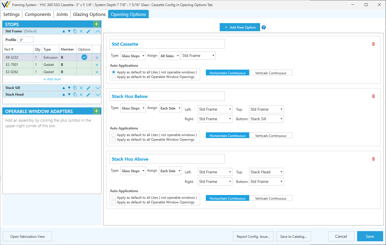
Standard Cassette
Type:Glass StopsAssign:All Sides,Standard FrameAuto Applications:
- Toggle on -
Apply as default to all Lites ( not operable windows )- Toggle off -
Apply as default to all Operable Window Openings- Set
Horizontal Continuous/Vertical Continuousbased on vendor requirements.
- This sets whether the horizontal or vertical framing takes priority for cuts at corners.
Expansion Horizontal Below
Type:Glass StopsAssign:Each Side
Left:Standard FrameTop:Standard FrameRight:Standard FrameBottom:Expansion SillAuto Applications- Toggle both of these off.- Set
Horizontal Continuous/Vertical Continuousbased on vendor requirements.
Expansion Horizontal Above
Type:Glass StopsAssign:Each Side
Left:Standard FrameTop:Expansion HeadRight:Standard FrameBottom:Standard FrameAuto Applications- Toggle both of these off.- Set
Horizontal Continuous/Vertical Continuousbased on vendor requirements.
Configure Joints
In the Joints tab, configure all joint conditions based on vendor requirements at different conditions. See Joints Tab for more details.
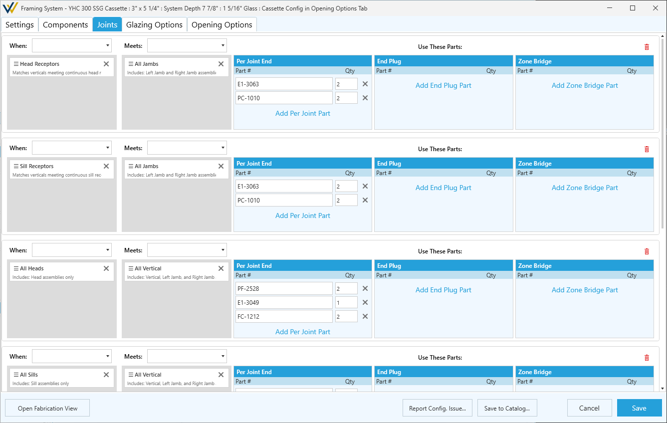
In most cases you'll need a joint configuration for each of the following:
- When
Head ReceptorsmeetsAll Jambs- When
Sill ReceptorsmeetsAll Jambs- When
All HeadsmeetsAll Verticals- When
All SillsmeetsAll Verticals- When Horizontal (default horizontal) meets
All Verticals- When Expansion Horizontal (see above) meets
All Verticals
Drawing Elevations
With these options configured, draw your elevations.
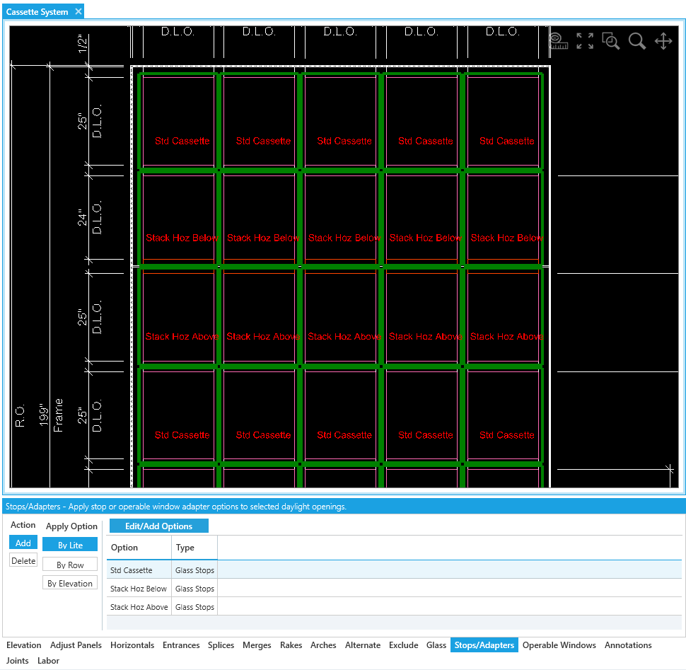
By default, your elevation have all panels set to the Standard Frame stops and the default horizontal option at all horizontal. From here, we'll apply the expansion horizontal and the alternate stops/adapters using tool tabs.
- For elevations where a vertical splice is needed:
- Using the
Alternatetool tab, apply the expansion horizontal assembly at the horizontal aligned with the vertical splice. - Using the
Stops/Adapterstool tab:- Apply expansion sill to the panels above the expansion horizontal.
- Apply expansion head to the panels below the expansion horizontal.
- Using the
As long as they're configured correctly, the joints should apply themselves. You can review them using the Joints tool tab.
See here for an example where a vertical splice has been added between the 2nd and 3rd row of panels: