Tips - Splices
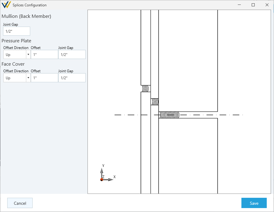
You can configure splice gaps (and offsets for pressure plate and face covers) by editing the assembly and going to the splice tab. See the following images for how to get to the configuration view
- Edit your framing system.
- Click the
Componentstab. - Click the
Editbutton on the assembly you want to edit. - Click the
Splice Tabon the right side of the assembly configuration window. - Click
Configure Splices
From this menu, you'll be able to set your joint gap and dial in your offsets for pressure plates and face covers, where needed.
Splices at Subsills / Head Receptors
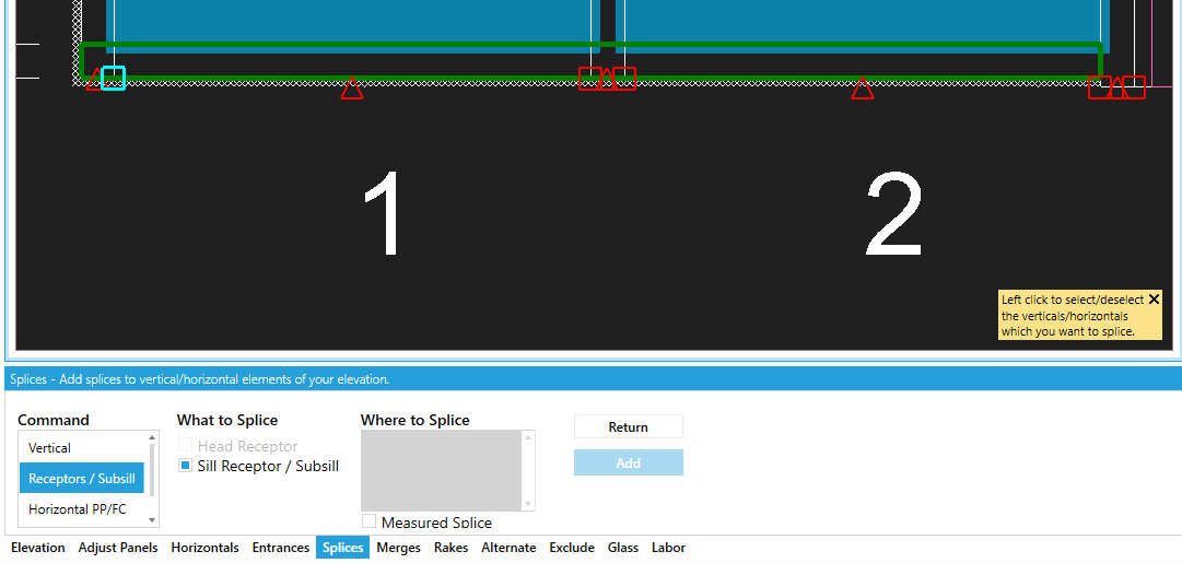
Head receptors, flashing, and other subsills can be spliced with adjustable gaps and hardware.
note
The Receptors / Subsill subcommand described below will only appear if your framing system is configured with a head or sill receptors.
- Select the
Splicetool tab at the bottom of the editor - Click
Add - Under
Commandselect theReceptors / Subsillsubcommand - Under
What to Splicecheck/uncheck theHead ReceptorandSill Receptorcheckboxes as appropriate - Select or enter your snap points
- To splice at a snap point (midpoint or edge of a panel or vertical), click one of the red squares (endpoint) or triangles (midpoints) that appeared on the head or sill.
- To splice at manual distance from the left edge of the elevation, check the box that says "measured splice" under the splice locations list area and enter the X value you want to splice at.
- Click
Addto confirm and apply the splice.
Multiple splice points may be selected when using snap points.
Vertical
- Select the
Splicetool tab at the bottom of the editor - Click
Add - Be sure the
Verticalsubcommand is selected - Select the verticals you want to splice (for more, see the note below)
- Under
Positionenter the splice height, measured from the bottom of the elevation. - Click
Addto confirm and apply the splice.
Note about selecting verticals:
There are many ways to adjust the vertical selection.
- By default, all verticals are selected
- You can enter comma-separated vertical numbers in the tool tab
- Use the
AllandNonebuttons in the bottom left of the drawing to help reset the selection set- Click on individual verticals on the drawing to toggle their selection
Pressure Plate and Cover
- Select the
Splicetool tab at the bottom of the editor - Click
Add - Under
Commandselect theHorizontal PP/FCsubcommand - Select or enter your snap points
- To splice at a snap point (midpoint or edge of a panel or vertical), click one of the red squares (endpoint) or triangles (midpoints) that appeared on the head or sill.
- To splice at manual distance from the left edge of the elevation, check the box that says "measured splice" under the splice locations list area and enter the X value you want to splice at.
- Click
Addto confirm and apply the splice.