Tips - Framing System Types
Tips
These configurations are officially supported in WinBidPro v16 but have some added set up when first configuring them. Follow these settings to get the most accurate counts.
Can / Stick Systems
For these, we want to have vertical assemblies enough extra length to slot into the head and sill. This is especially important for raked elevations.
-
Head Assembly/Sill Assembly- Set the
Revealto 0"
- Set the
-
Head Receptor/Sill Receptor-
Set the
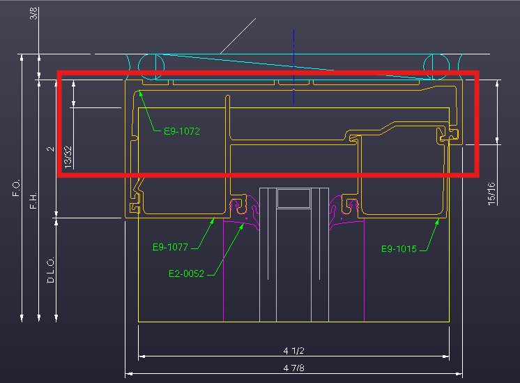
Vertical Trimto the dimension from the base of the receptor profile to the end of the vertical. -
In this example, the vertical is drawn in yellow. The 13/32" dimension is what we want for the
Vertical Trim.
-
SSG Systems
These are some additional settings made to handle SSG conditions.
-
In the
Settingstab, set yourSSG Type. Options include:NoneVertical SSGHorizontal SSG4-Sided SSG- (vertical & horizontal)
-
In the
Componentstab, toggleIs SSGin your vertical / horizontal assemblies.- Set the
Silicone Widthfor each assembly.
- Set the
-
See also - Tips - Face Covers / Pressure Plates.
Tricks
These configurations are not supported with dedicated settings, but you can approximate them with these settings.
Butt Glazed Systems
The key for these systems is to set a continuous head and sill receptor, then create verticals / jambs with small profiles and no glass bites.
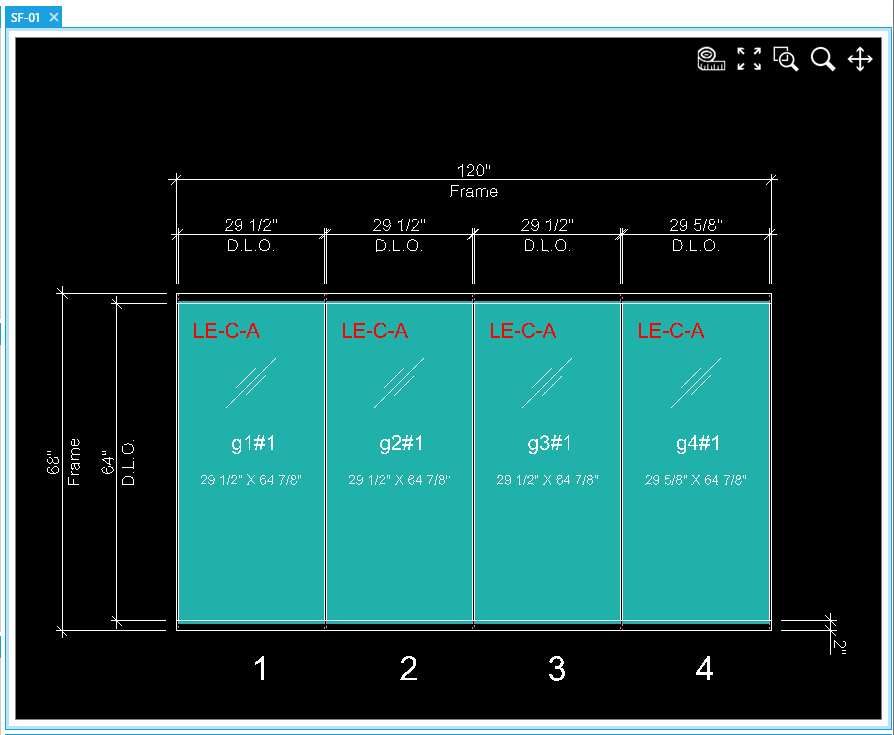
-
In the
Settingstab, toggle onHas Head ReceptorandHas Sill Receptor -
In the
Componentstab:-
Head Receptor/Sill Receptor- Add your head and sill extrusions here to make them continuous.
- Match the
Vertical Trimto theProfiledimension.
-
Head Assembly/Sill Assembly- Leave these assemblies empty.
-
Vertical Assembly/Left Jamb Assembly/Right Jamb Assembly- Create a new assembly.
- Set
Profileto the recommended size of the gap between glass lites. - Set
Glass Biteto 0" Parts- For silicone spacers, add or create a new part via the
+Browse Listbutton- See Configuring Parts for more details.
- For an air gap, you can leave the parts list empty.
- For silicone spacers, add or create a new part via the
-
Brake Metal / Structural Gaps
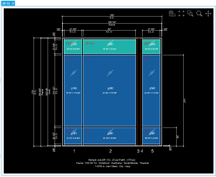
By creating extra panels with 0" widths, we can triple up verticals and set the middle vertical to an alternate assembly to represent a structural gap.
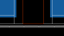
This trick should only be used for visual reference, not for cost estimation. Verticals cannot interrupt head / sill receptors so the counts for receptors and brake metal will not be entirely accurate. See image on the right for reference.
For accurate frame estimates, a structural gap should be excluded and the framed openings on either side should be separate elevations.
-
In the
Componentstab:- Create a new
Vertical Assembly- Do not delete the existing assembly or change the default.
- Name the assembly something easy to recognize like
Brake Metal - Set the
Profileof your new assembly to the width of the gap. - Toggle on
Interrupt HeadandInterrupt Sill.
- Create a new
-
In your Elevations:
- Add two panels in the
Elevationtool tab. - For the panels on either side of the gap, add set the panels to a fixed width of 0" in the
Adjust Panelstab. - Set the middle vertical to the new assembly using the
Alternatetab.
- Add two panels in the